To enable us to fabricate during the time of COVID-19, ITP sent the subtraction class Silhouette Cameo 4 vinyl cutters. I have been doing almost daily experiments with it, almost always on non vinyl materials. Below are a selection of the projects I have worked on over the last 7 weeks. From cutting lenticular lens, to plotting generative art, the Cameo 4 has turned out to be an extremely versatile machine.
Cutting Dichroic Film For Portraits
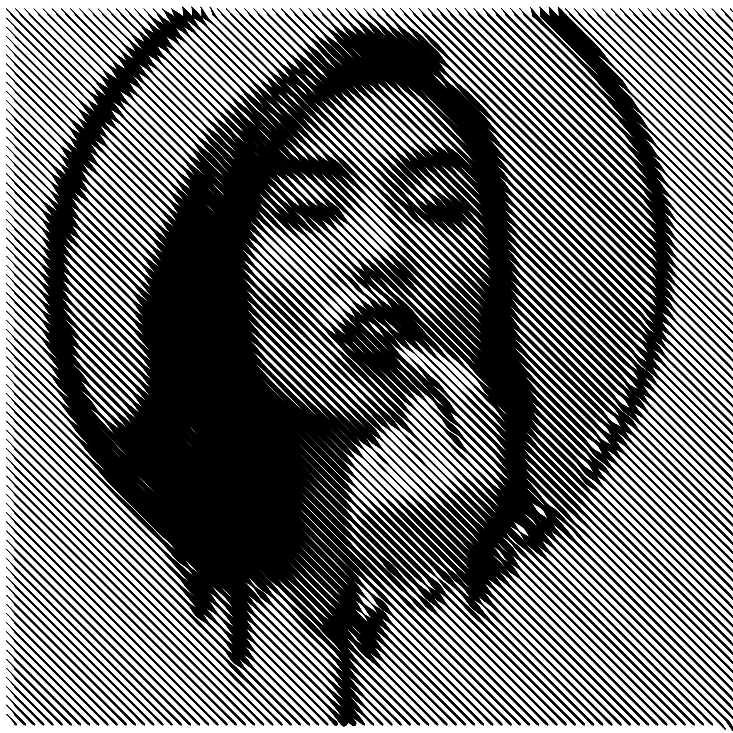
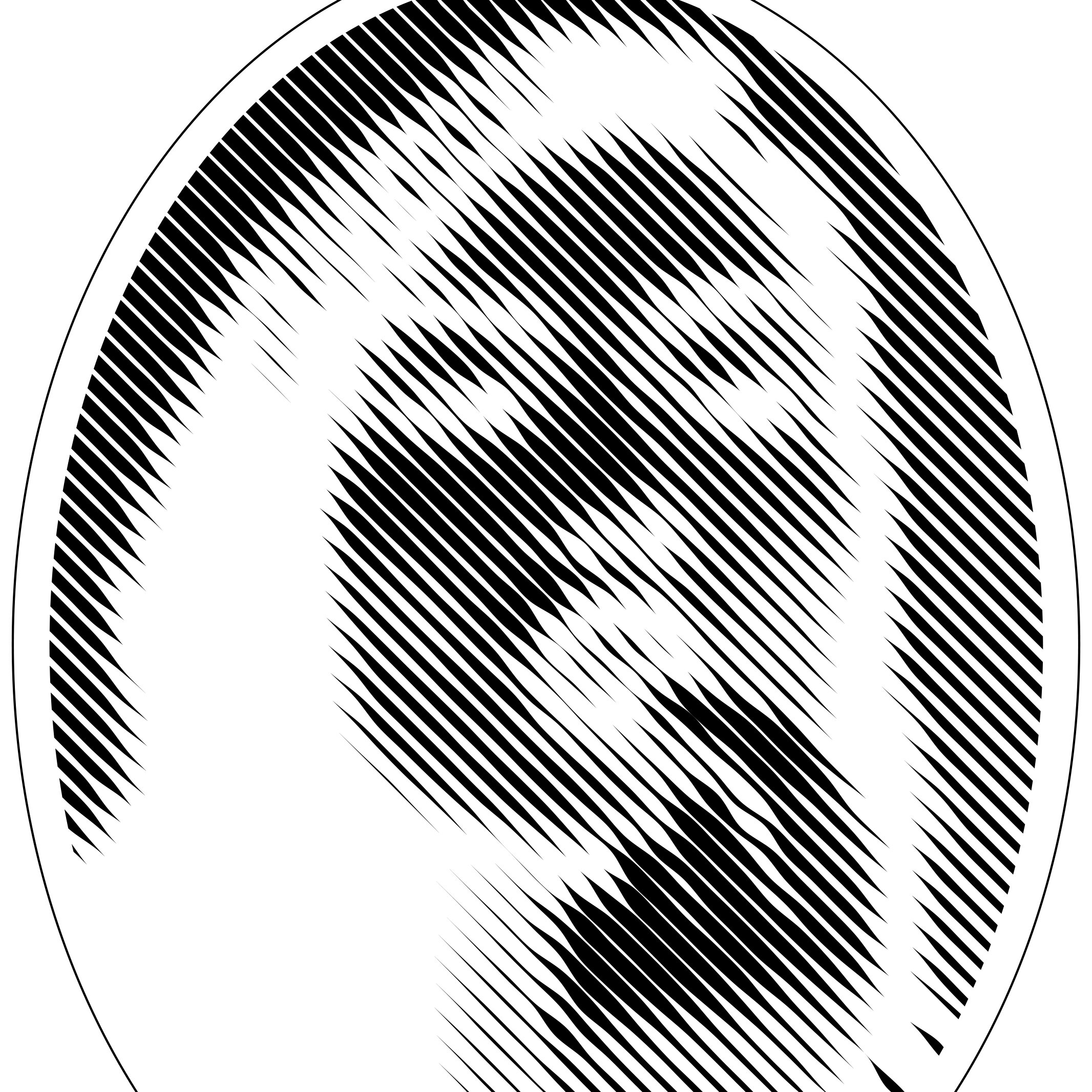
This week I took a program I wrote for Pixel By Pixel for turning images into halftone / particle simulation dithering vector files and used the output in the vinyl cutter to make a dichroic halftone portrait. The program generates files using Cartesian ellipse halftone, radial ellipse halftone, vertical, horizontal, and diagonal line halftone, as well as a variety of particle simulation dithering.
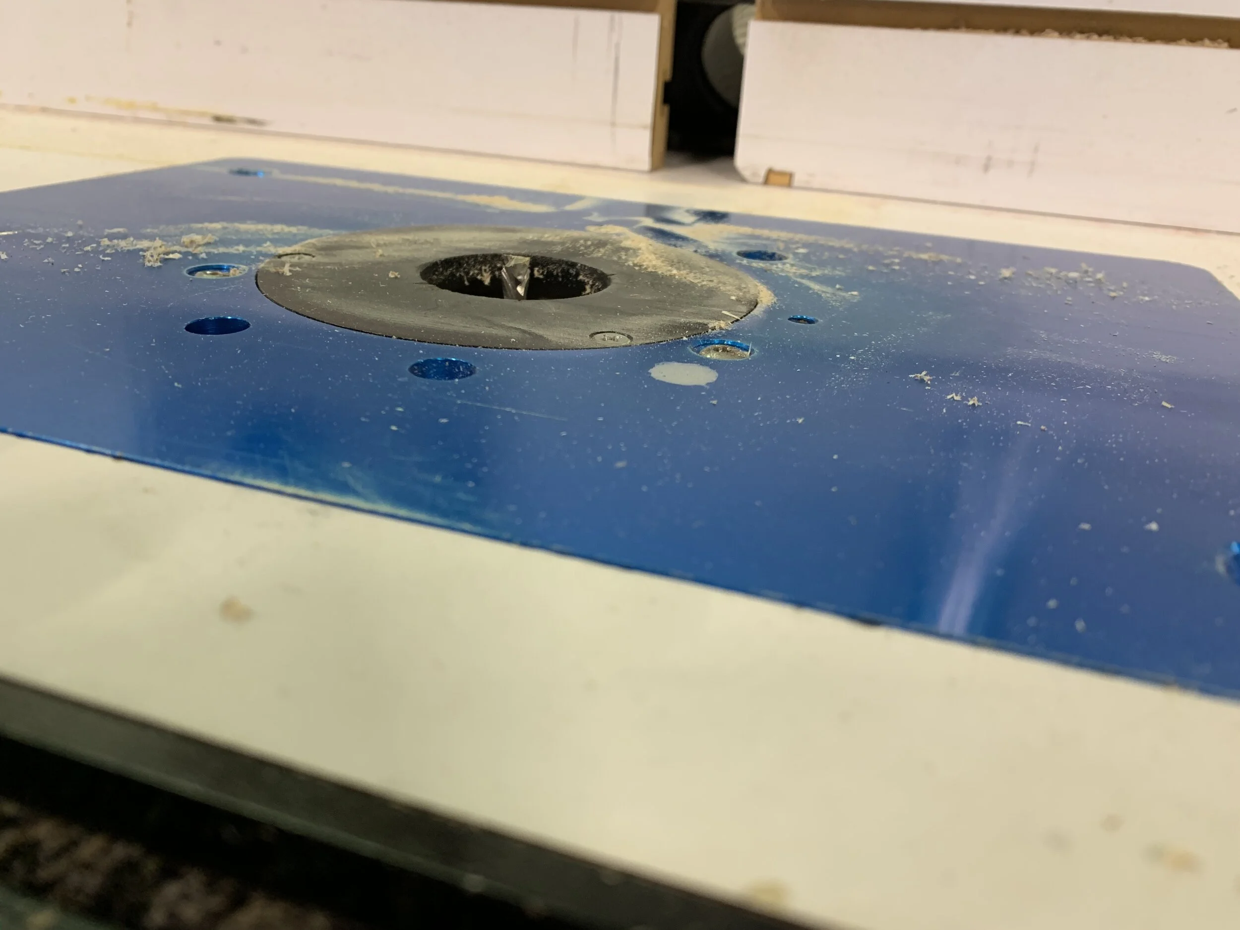
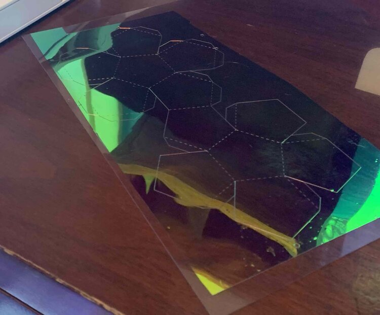
It turned out that only the halftone line outputs could be cut on the cameo, the ellipses and the particles get pulled off of the cutting mat when the blade lifts between cuts. This is a problem is that the vinyl cutter is cutting the dichroic film but not the sticky backing behind the film so that it can later be pulled off of the dichroic once it is off the mat and on transfer paper. If we cut all the way through, the circles stay on the cutting matt but we can’t take the dichroic backing off and therefore can’t stick the non peeled away parts to anything.
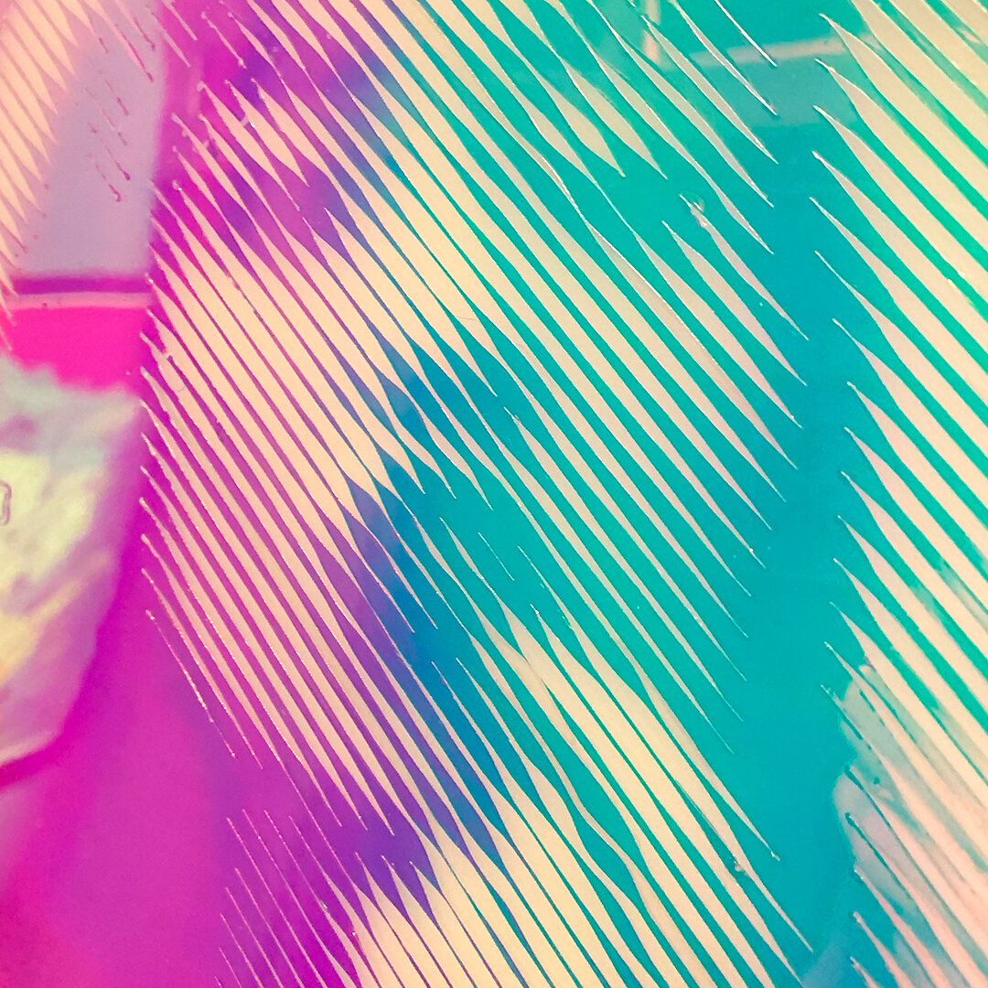
The images below show the input to the program, the vector output, and the illustrator file that gets sent to the Cameo. The output appears to be the inverse of the image because the dark spots are the pieces that get cut and removed from the film leaving the white spots as dichroic film which appears to be the shaded part of the image in the end.

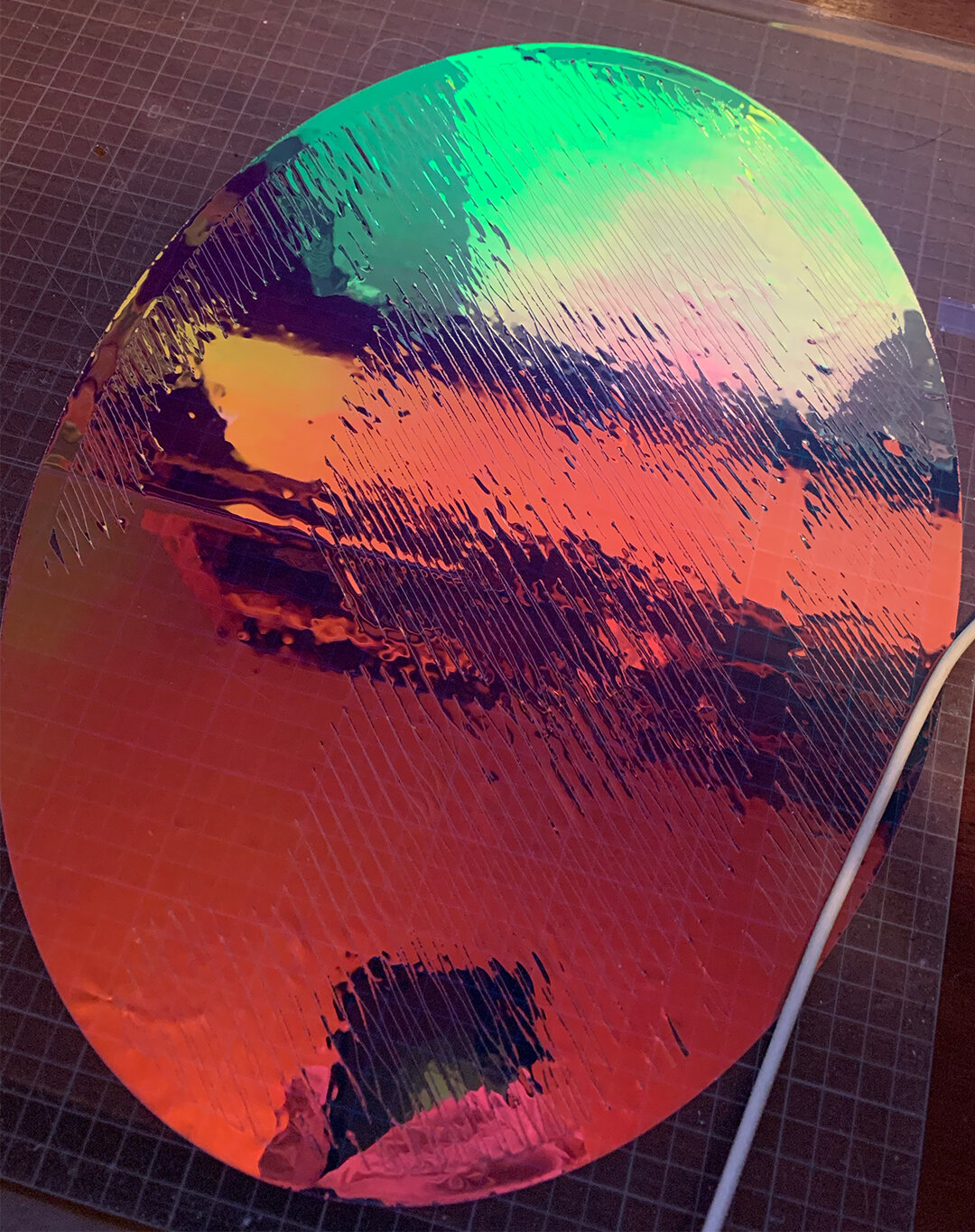
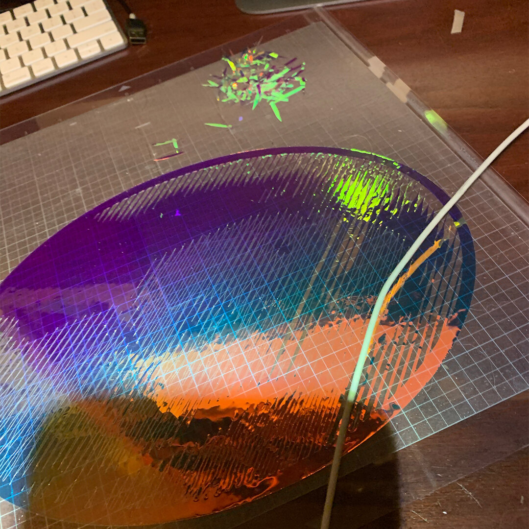
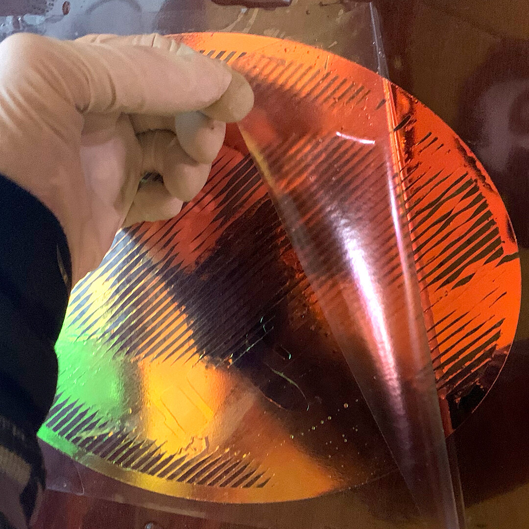
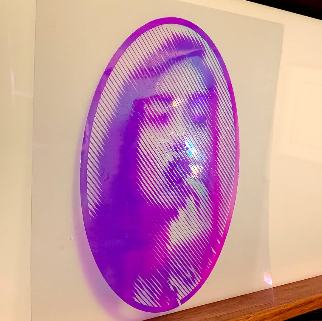
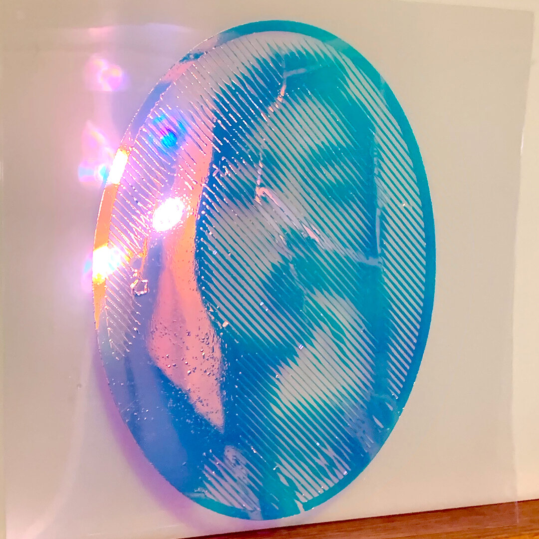
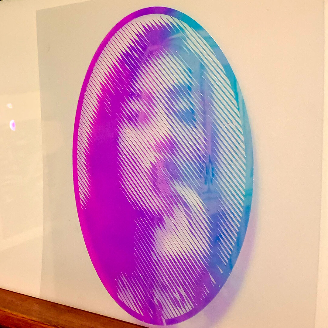
Below: Left: Dichroic film on cutting mat after vinyl cutting. Middle Left: peeling off dichroic strips (backing is left behind in the gaps). Middle Right: result of transfer paper being applied to cutting matt and pulling off left over dichroic film and taking the backing off of the film. Right: Dichroic applied to plastic pulling off the transfer paper.
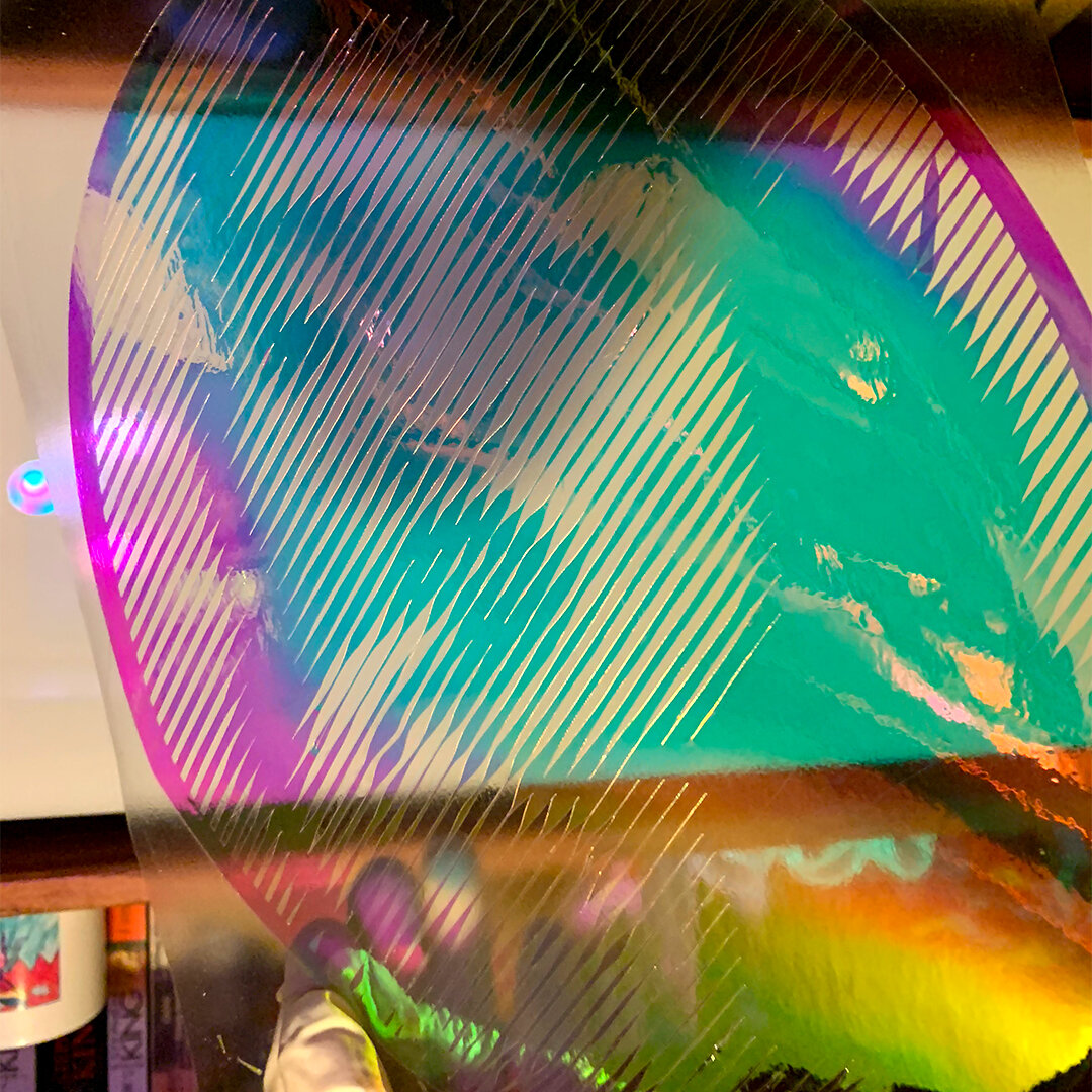
As you move around the image, it changes colors, and appears more clearly the farther away from it you are.
Plotting Perlin Noise
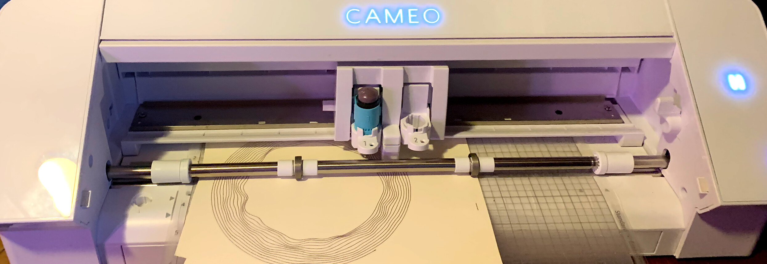
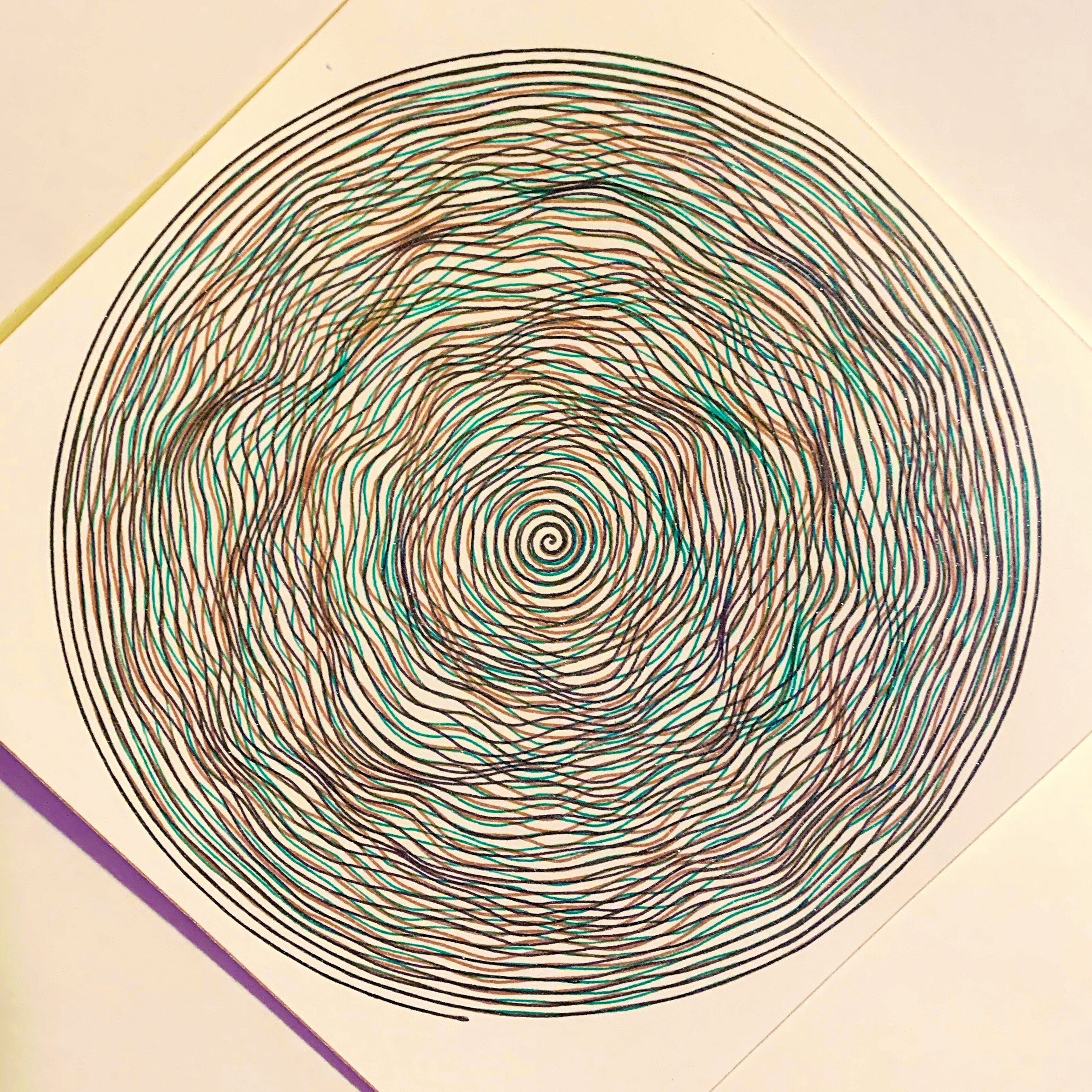
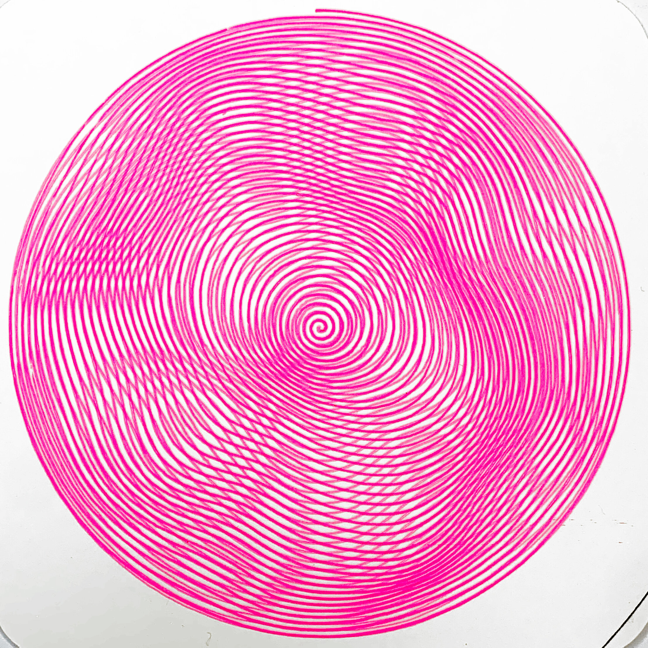
This week I also did some tests with the plotting attachment to the Cameo. I have a set of pens which came with the cameo. I found a program written by an artist named Daniel Catt which allows you to set parameters to generate Perlin noise spirals. These spirals can be overlaid on top of each other and plotted. The results are 3D- looking noise blobs that are quite satisfying to look at and move around.
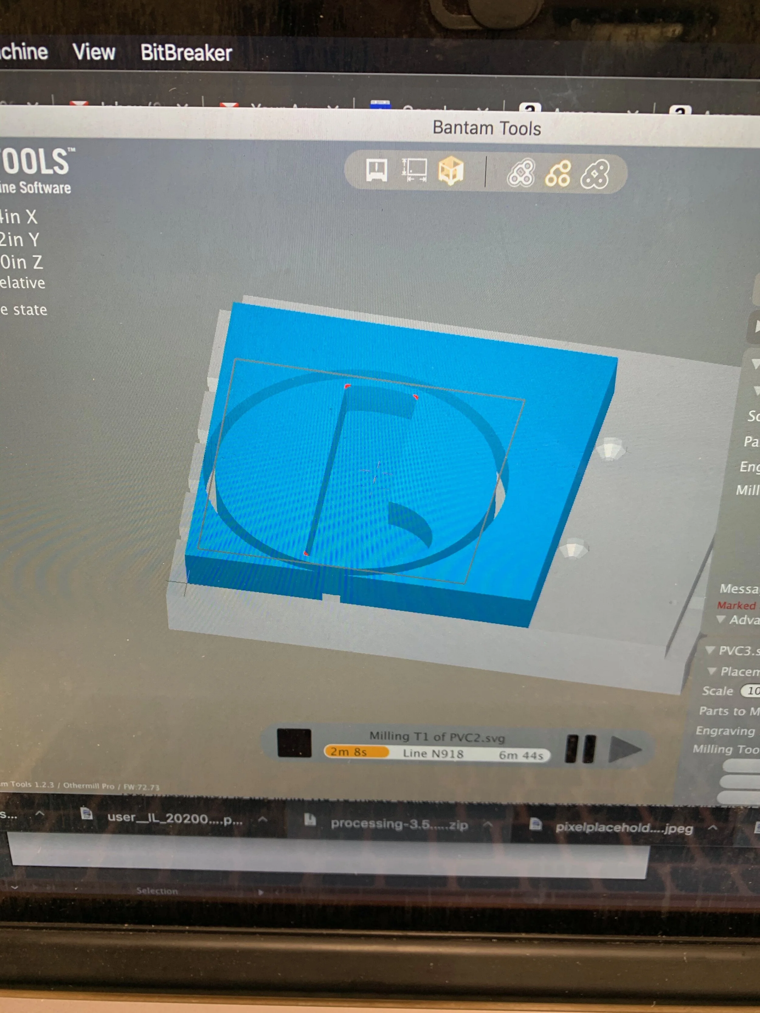
The images below show the UI of the program and the overlapping results in illustrator. The output of the program is a svg with 20,000+ points, you define how many segments you want but they only appear to impact rendering in the browser not in the svg. In order to import into silhouette studio, I had to simply the path in illustrator to 2000 points. More points than this, silhouette studio crashes, as is, it takes minutes to generate the cut path. This summer, I plan to rewrite the program myself in processing so that it is more responsive and you can simulate vinyl cutter output before wasting time and materials on cutting. I am eager to try plotting with better paper and better pens. I ordered a pen attachment and some architectural technical pens. The pens that came with the Cameo are pretty bad. They often bleed across the paper before the first path is drawn (you can see the artifacts in lots of the photos below), other pens run out of ink right away, overall the color selection is mostly neon and sparkly colors, none of the primary colors worked (bled or didn’t draw at all).


The first attempt came out best. The color combinations add to the optical illusion of depth.
The colors on the second attempt didn’t work as well as the first try, these were the sparkly pens.

Not Perlin noise - a simulation of the movement of Neptune and Uranus I used to test out the drawing settings.


Cutting Lenticular & Dichroic Lamp Shades
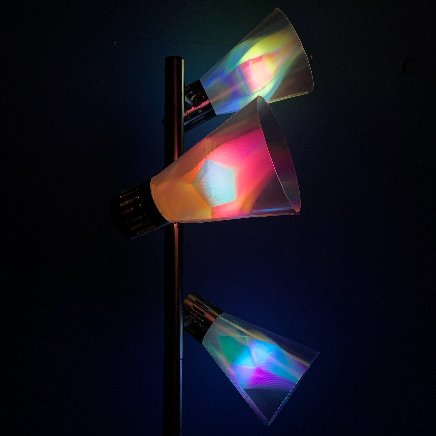
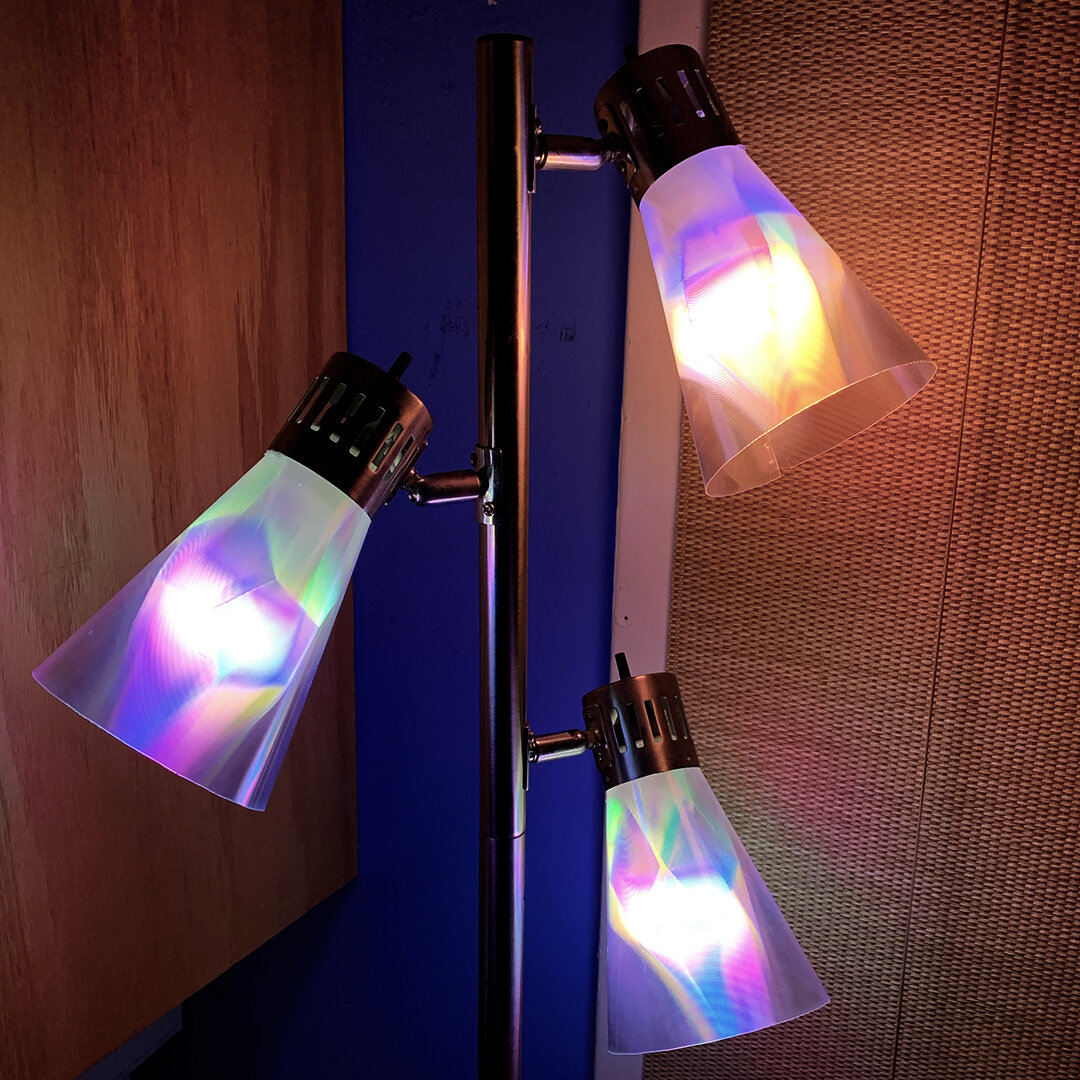
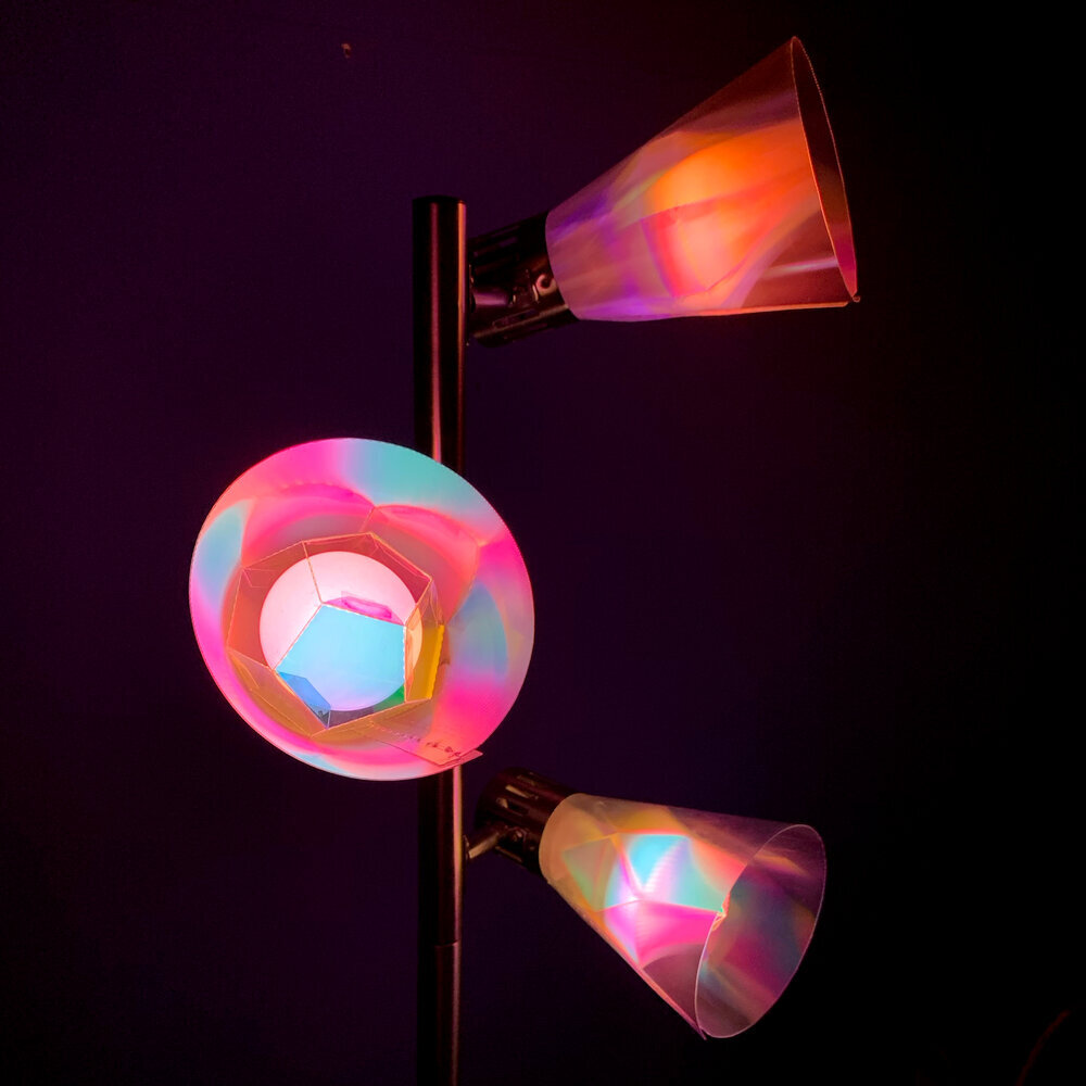
I also used the vinyl cutter this semester to create a light fixture I call Times Square Hue. This piece uses live webcam data from times square and maps the colors that the webcam sees to the color and brightness output from three hue bulbs. The webcam data comes from earth-cams.com, I am using OBS as a virtual webcam grabbing the browser data and sending that as the input into a processing program. The processing program breaks the image up into thirds vertically, and scans across each third with a box 1/4 the screen width. The average color (after thresholding and saturating) from that frame get sent to the corresponding hue bulb.
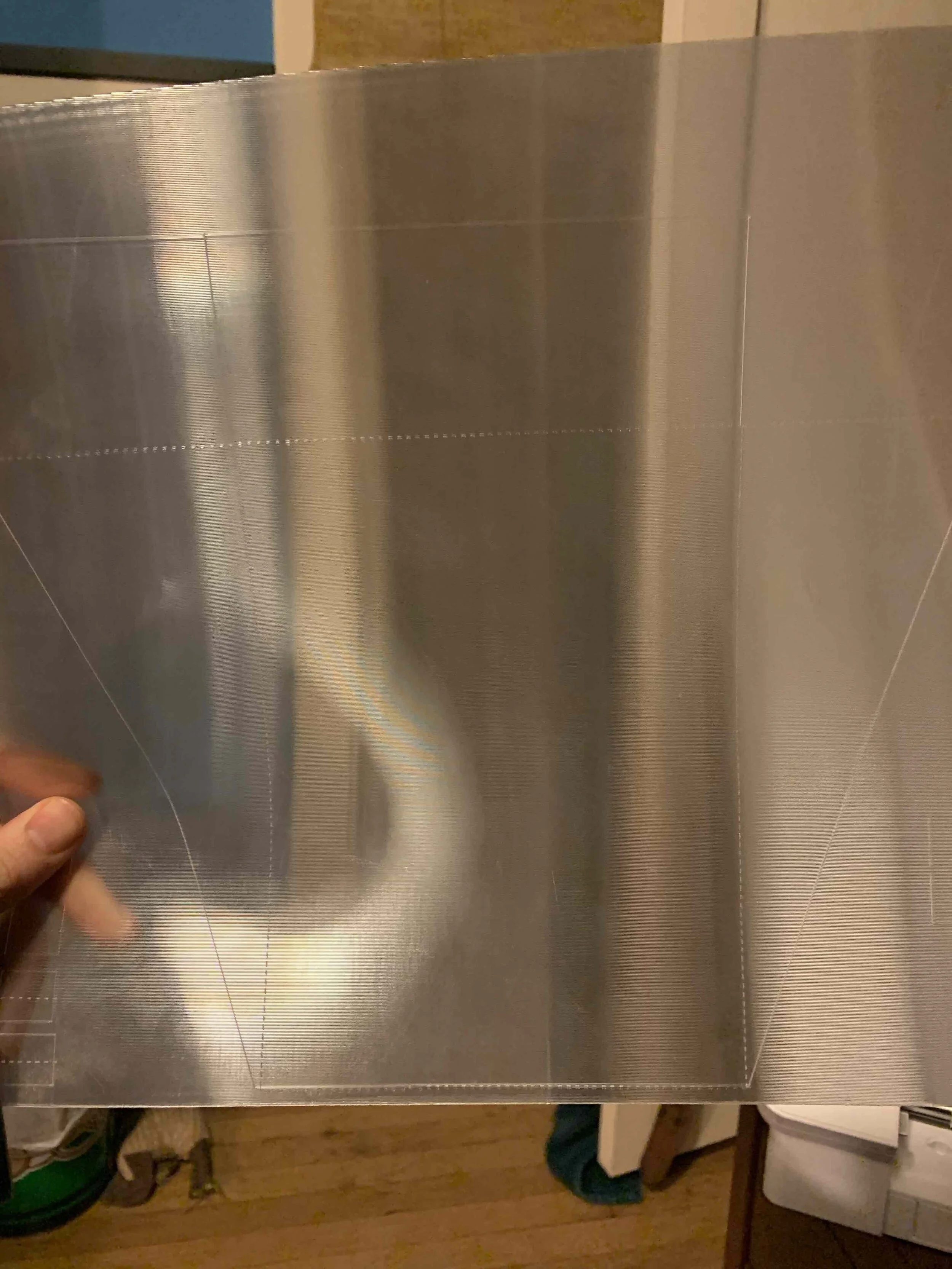
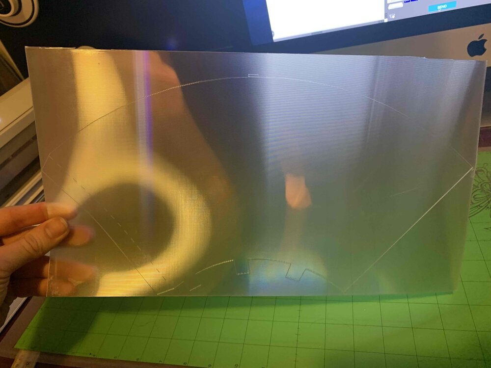
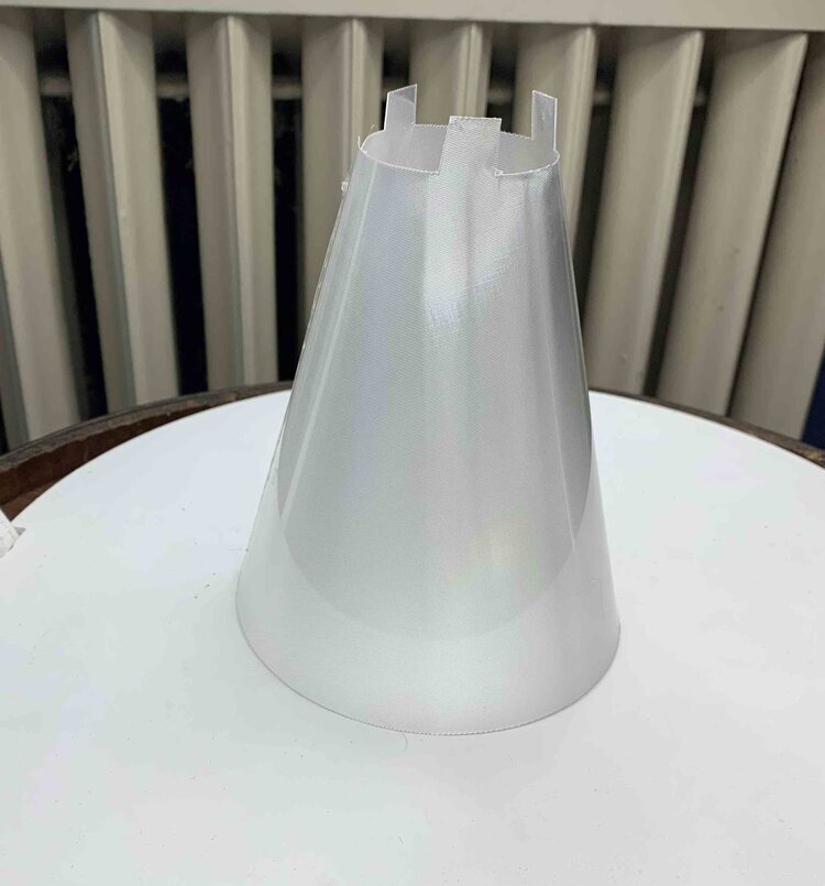
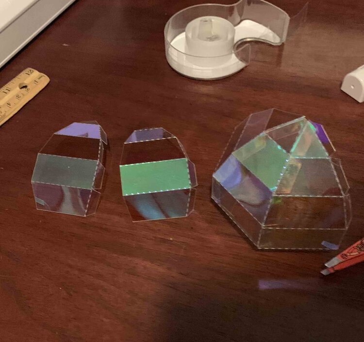
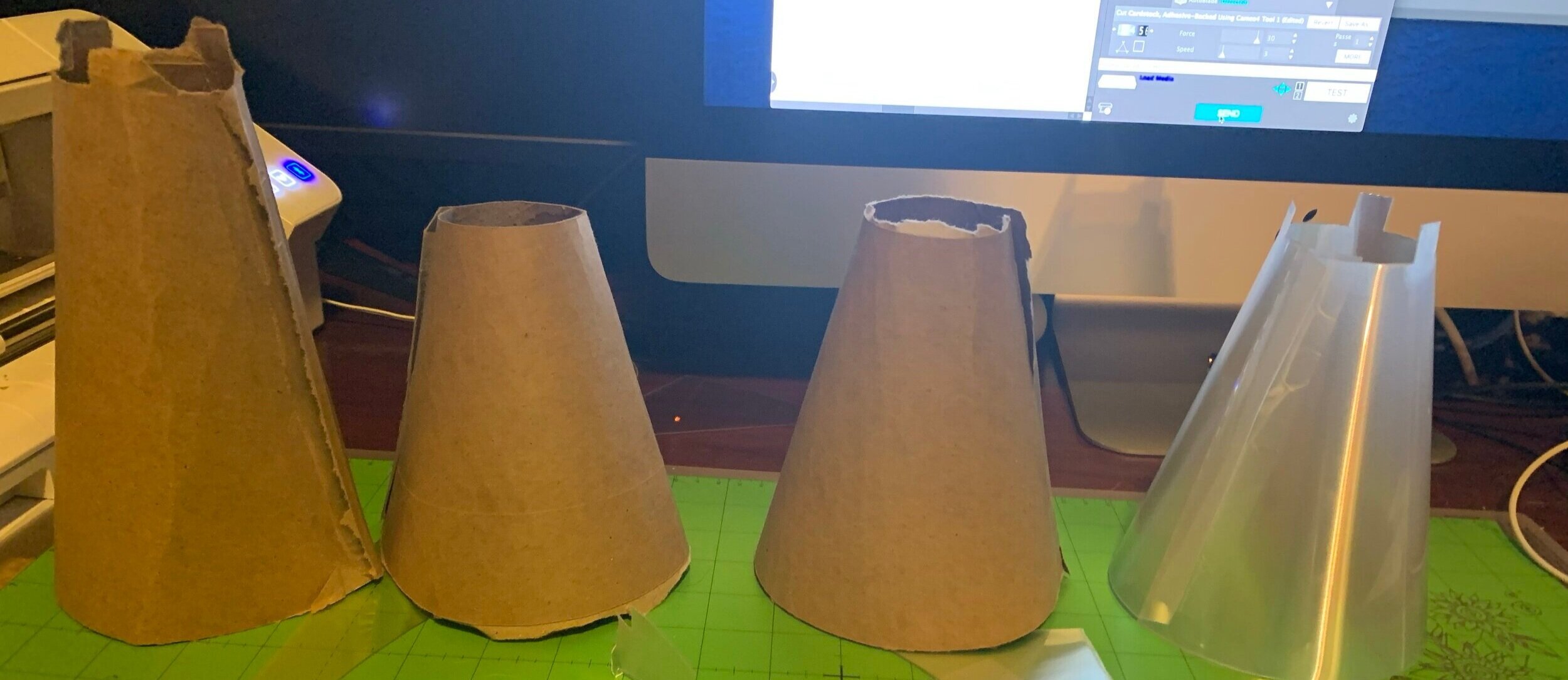
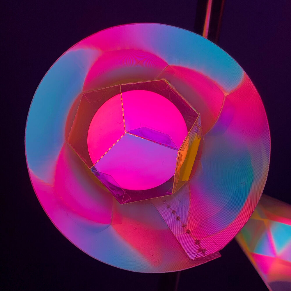
This fixture is made of three open cone shades made from lenticular lens around platonic solids made of dichroic film applied to thin plastic sheet. Lenticular lens is an extruded plastic sheet where one side is embossed with columns of tiny corrugations called lenticules, hence the name "lenticular" in lenticular extruded lens. The lenticules are all the same size and are spaced equally across the sheet. The other side of the sheet remains smooth in order to be printed upon. The lenticules are half cylinders that cause the light to be magnified in one direction. This is commonly used in printing images which hold multiple frames that have variable visibility based on the angle you are viewing from. In this case it is stretching the light along the plane of the light bulb height. The dichroic film selectively allows certain colors to pass through and reflect other colors. This effect is due to a phenomena called thin film interference; when light passes through a film, some waves are reflected by the film boundaries causing some wavelengths to be amplified and others to be cancelled out. The light colors that are visible on the lenticular are based on the hue colors filtered through the dichroic film.
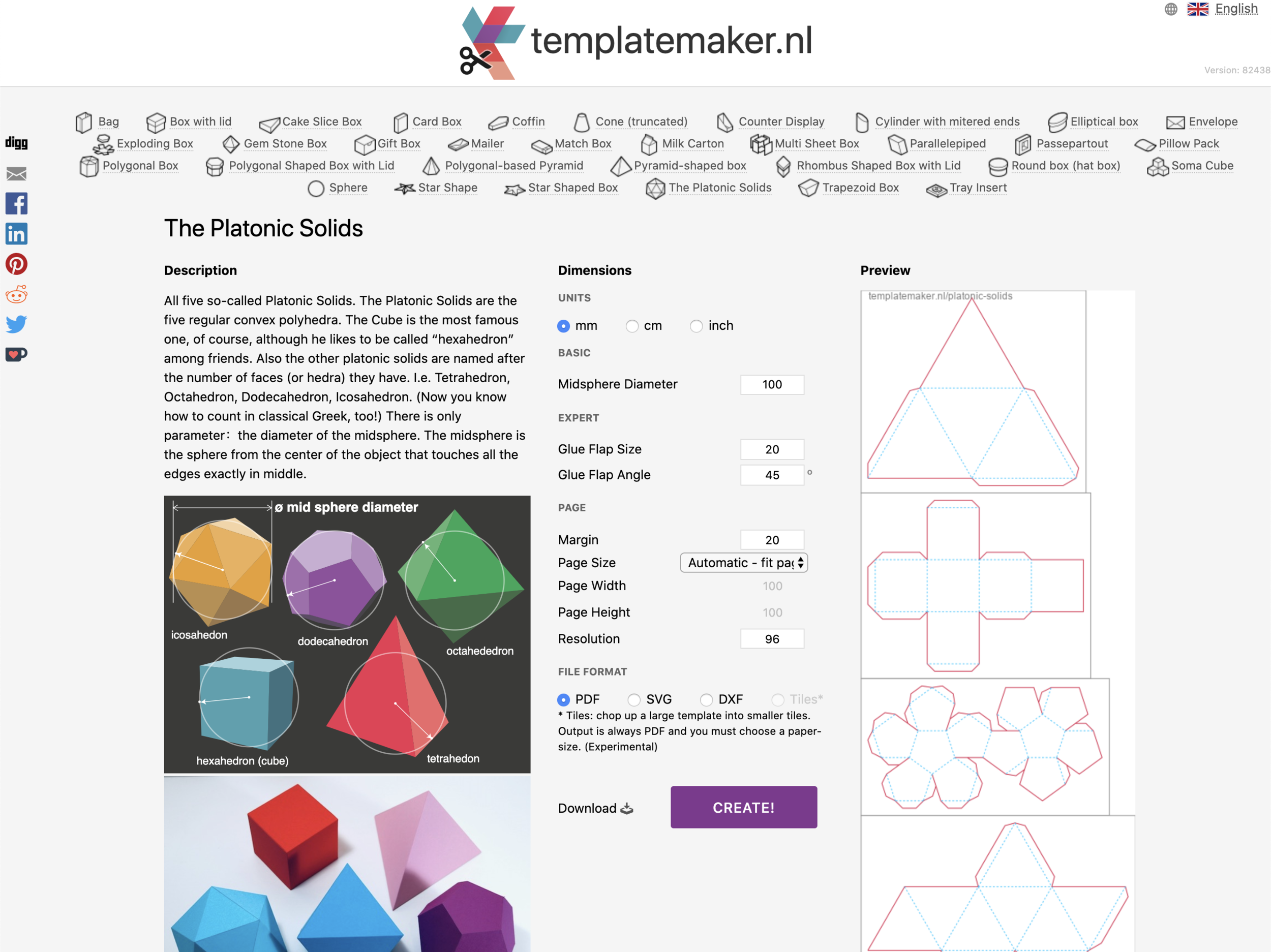
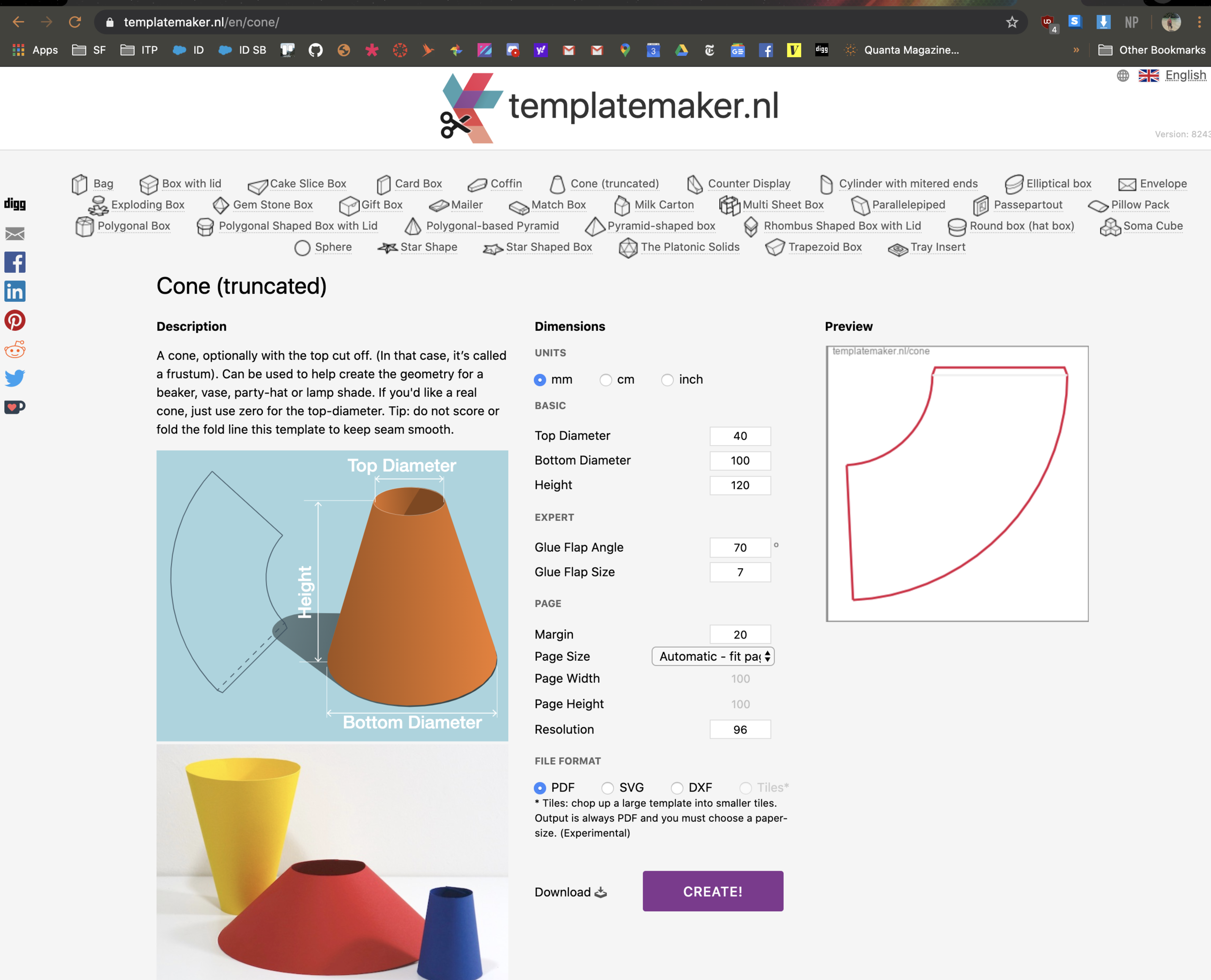
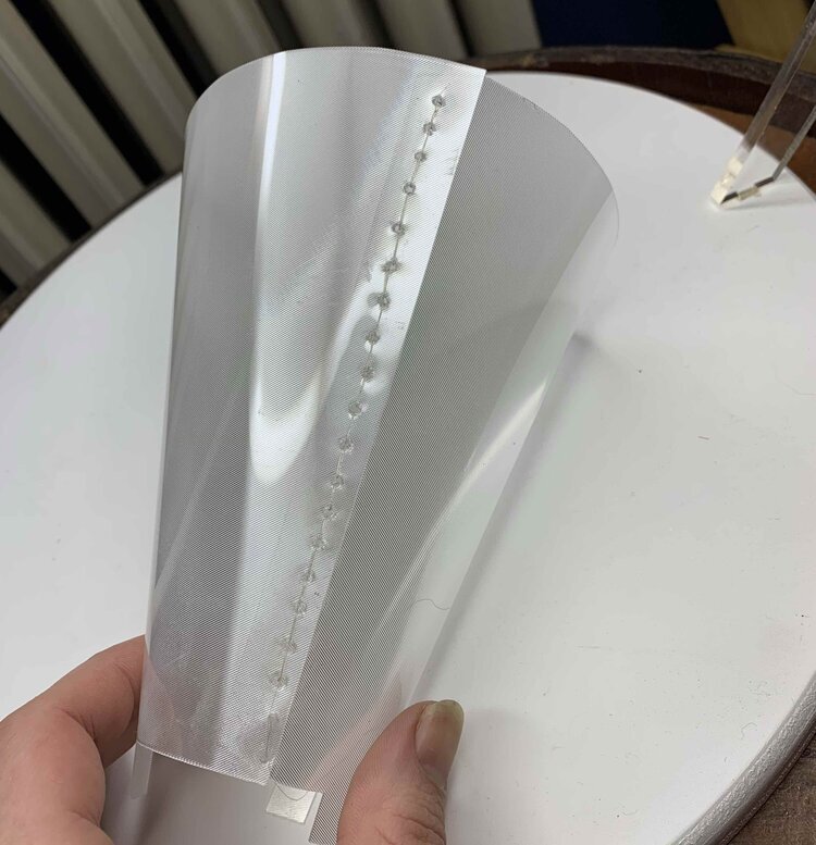
I used Templatemaker.nl to generate cutting files for the platonic solids and cones. It took quite a bit of trial and error to get the right sizes. I sewed the lenticular cone together with fishing line and glued the dichroic platonic solid tabs.
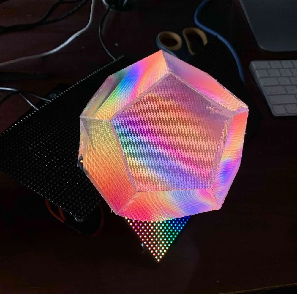
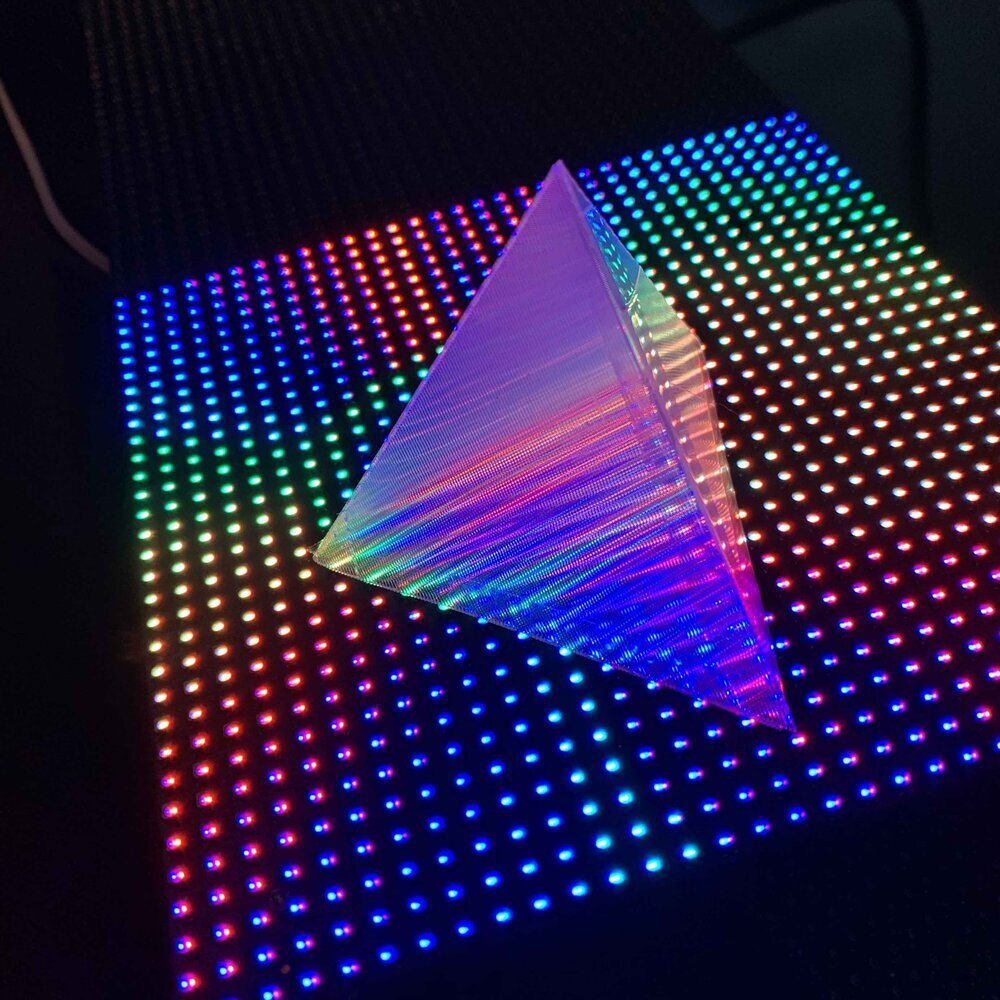
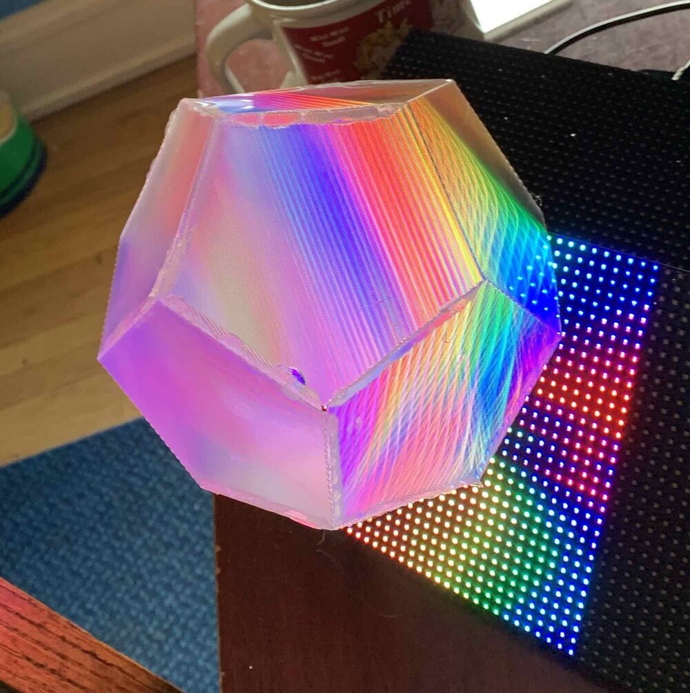
Lenticular Platonic Solids On Video Screens
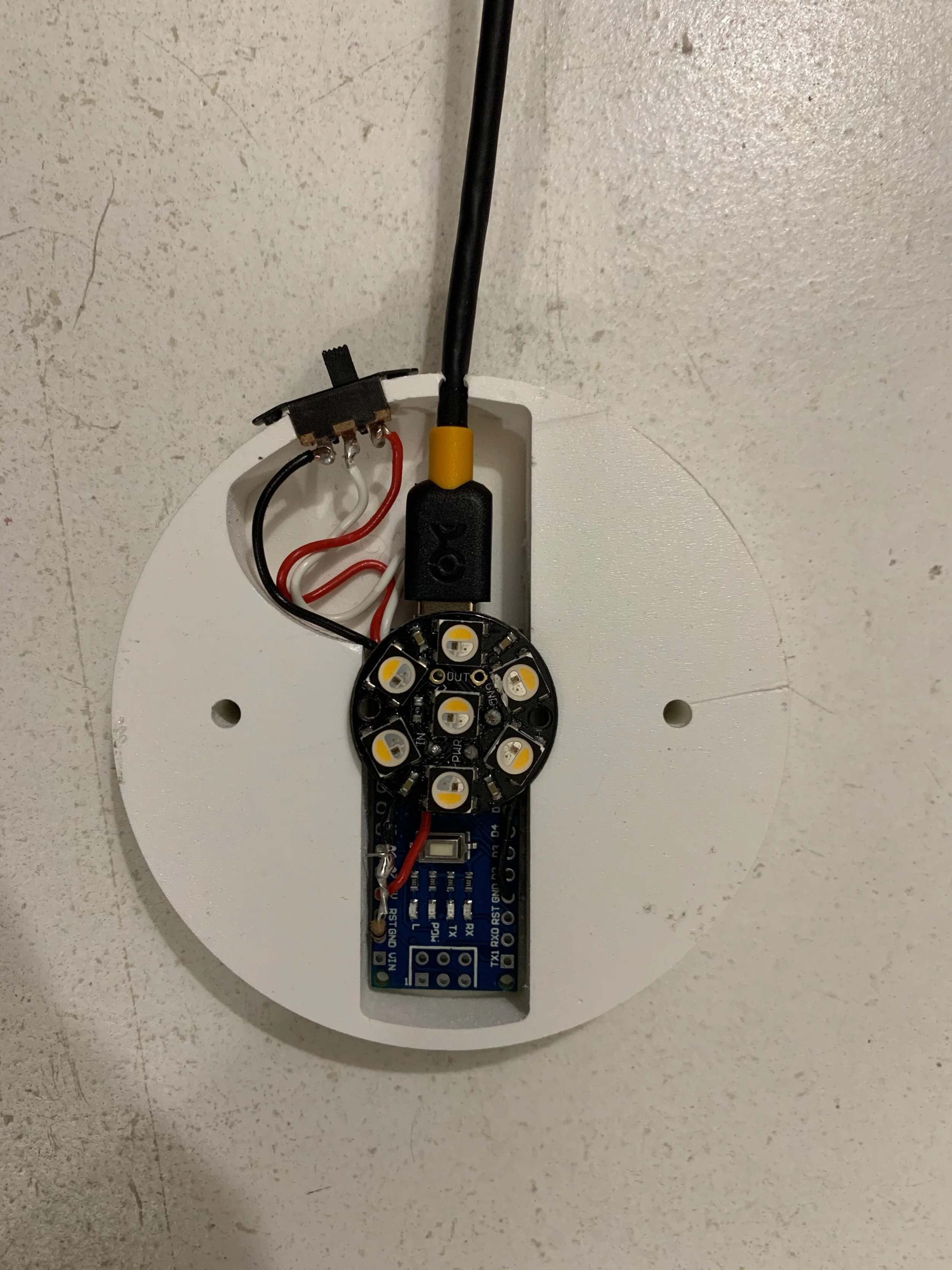
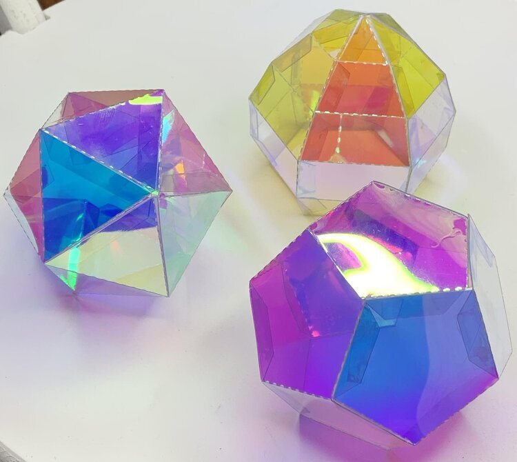
In addition to making lenticular cones, I created a series of platonic solids out of lenticular, and placed them on top of led matrices. The led matrix is controlled by a raspberry pi and a adafruit RGB Matrix Hat and RTC. I am looking forward to continuing experiments with this setup over the summer.
The platonic solids paths are generated using templatemaker.nl. Then they are sent to the Cameo 4 vinyl cutter which is not strong enough to cut through the lenticular, but is strong enough to score it deep enough to later peel apart the film. I tried hot glue, super glue, and tape as method of fixing the edges together. None of them are satisfactory methods or clean enough for my standards. I am going to experiment with fusing the edges together with a soldering iron over the summer, it worked on the cube platnoic solid but is going to take a lot of practice and experimentation to get a consistent edge on the bigger shapes.